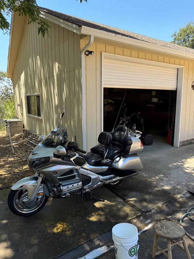
I thought I’d use the term Pulse Generator instead of the other commonly used “ignition pulse crankshaft position sensor”.
I started this Friday evening to get a start on the tear down.
The front upper and center cowling requires removal to perform this project. I didn’t have to remove the front fender, I drape a towel over it for some form of protection.
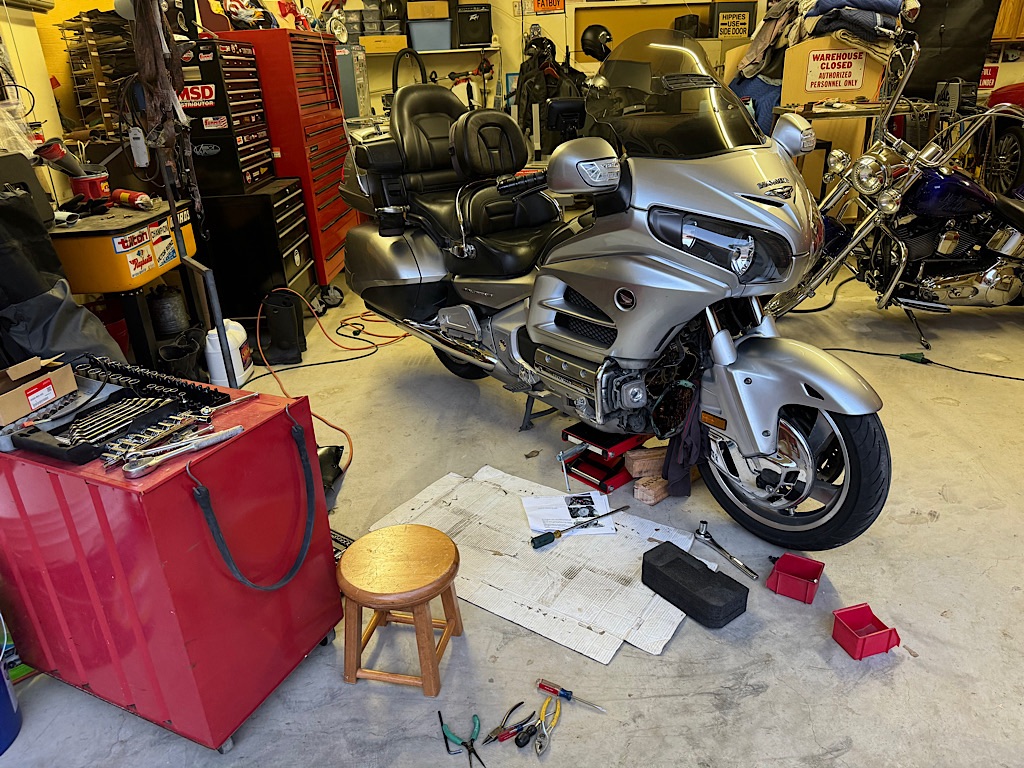
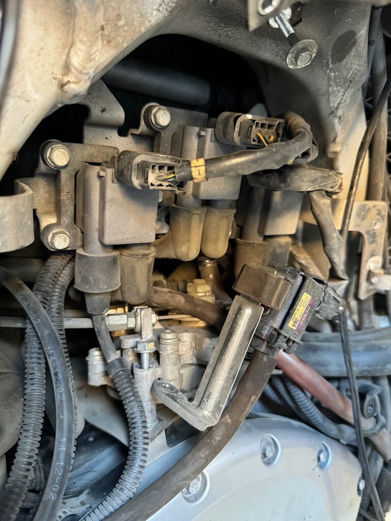
Once the front plastic pieces are removed you’ll see the regulators and purge valve located at the upper section as shown in the photo below. I have the non-ABS model and it is not necessary to go from above to access the Pulse Generator 2P connector. Everything will be done from the front of the engine.
The following instruction was taken from an online Goldwing forum. I did not create this procedure but I can say it is what I used to perform the part replacement.
Here are the instructions from Greg:
“If you have ABS, you’ll need to pull the tank and air box to get to the 2P connector.
If not, remove the upper center cowl, the single bolt and vacuum hose, to allow the canister’s purge control solenoid to fall. Then unplug the on each side. Wrap the coils in a towel and allow the coils to fall on the the back part of the front fender. That should then give you access to the boot the connector is in”.
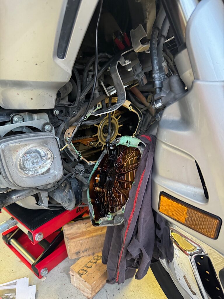
Once the purge valve and regulator housing has been loosened and moved forward the Pulse Generator 2P is accessible for removal.
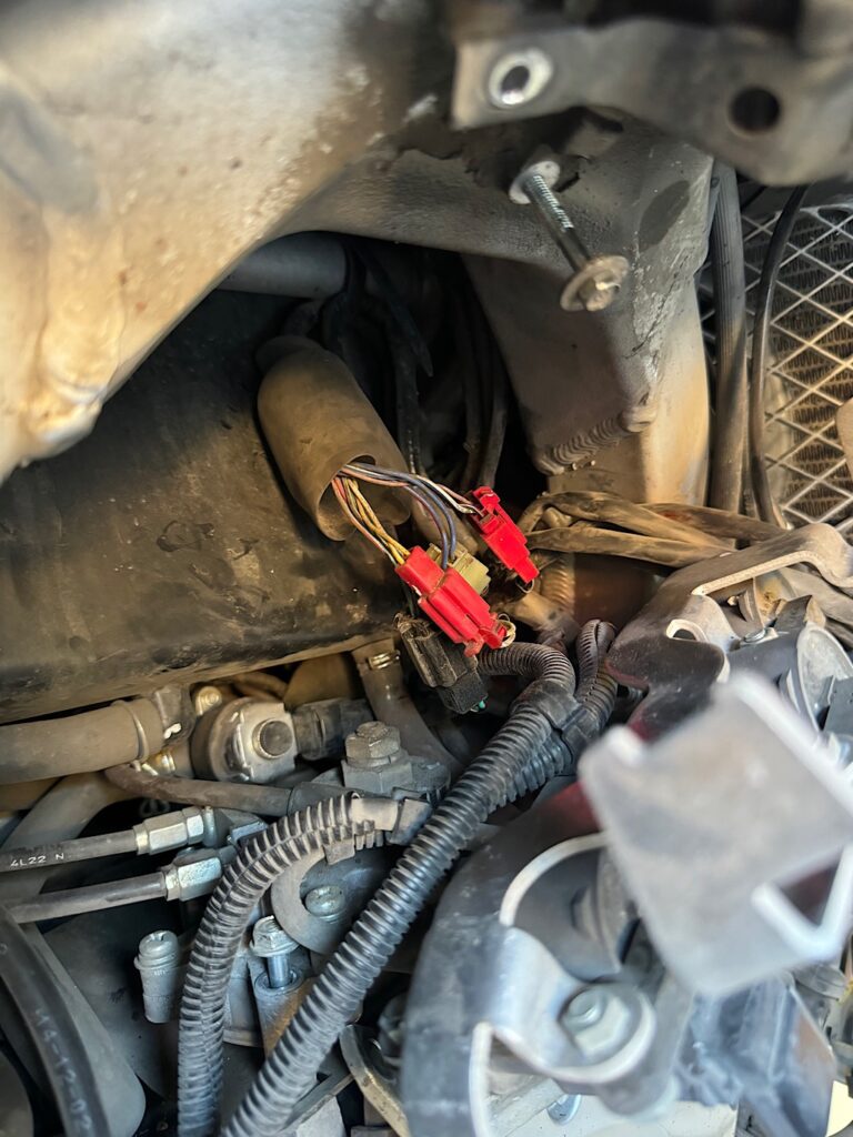
The 2P is bundled with a few others wrapped in a dust boot. You will need to slide the boot cover out of the way to unclip the mating connector.
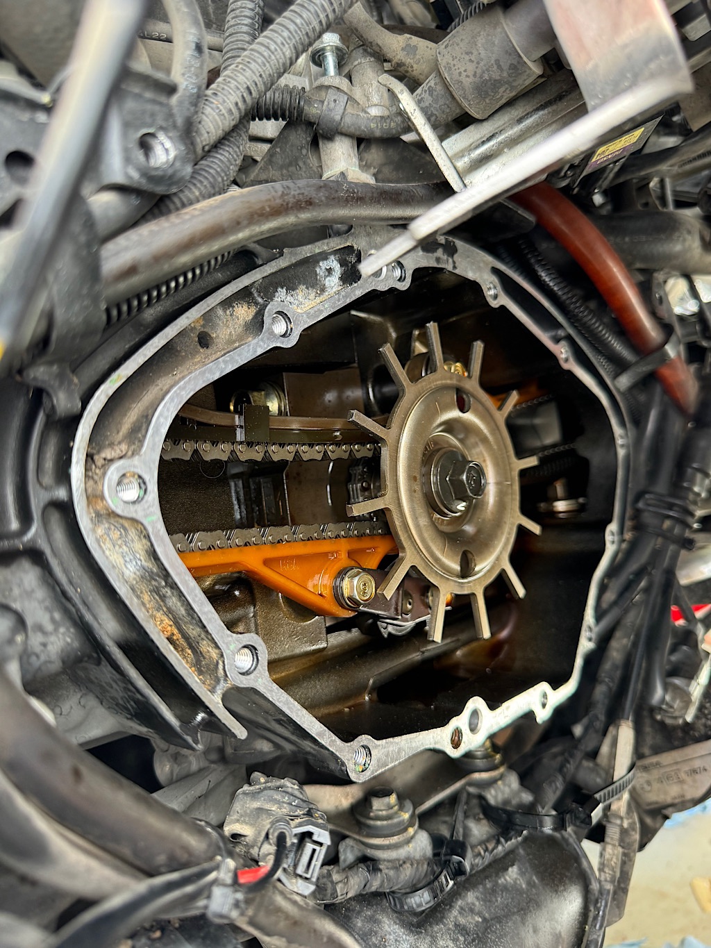
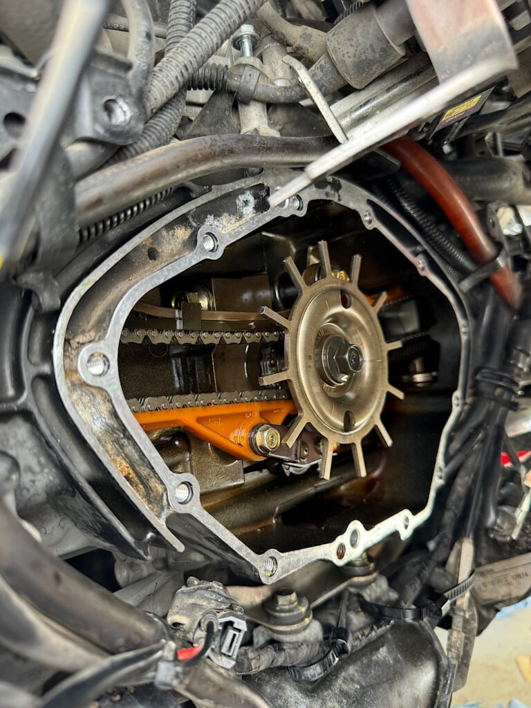
To access the pulse generator, the timing cover will need to be taken off. This is done by removing the 12 cover screws. You do not need to remove the crankshaft center dust cap. The cap can stay in place during the entire process.
In my case the timing cover has probably never been taken off. It was difficult to remove by hand. I ended up having to use a large blade screw driver to pry the cover off.
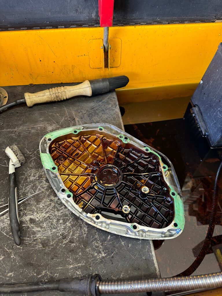
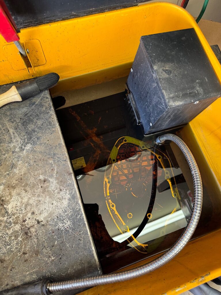
As expected pieces of the original gasket remained in place. With a bit of elbow grease and soaking the cover inside my parts cleaner tub, I was able to remove all the pieces.
The engine housing also required gasket material removal. Since I’m not able to have the same luxury with the chemical tub application I used engine bay cleaner to soak the remain8g pieces. I take my time whenever I work on projects for the first time.
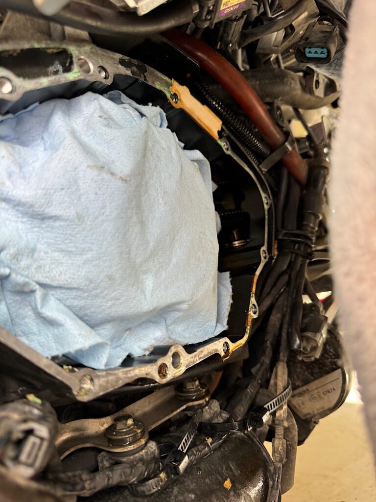
Case cleaned up and ready for the new part.
The pulse generator will be prewired to a 2P connector. I went ahead and bolted the part down and positioning the wires through the slotted opening. Once that is complete you can lay the gasket onto the timing cover using the 2 dowels for gasket alignment.
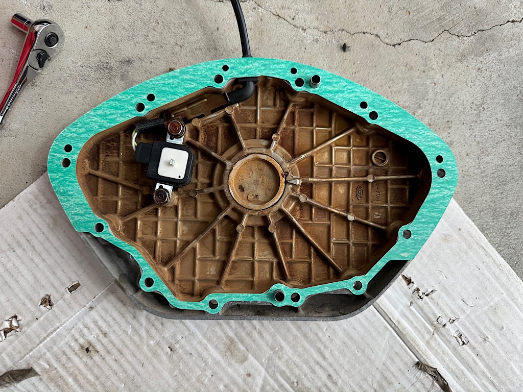
The installation procedure is essentially doing everything in reverse order. After buttoning the timing cover back in place and securing the regulators and purge valve I did a test start. It fired right up.
After installing the remaining pieces I gave the sled a wash. All ready for the next ride!
