DTC – Diagnostic Trouble Codes

Reset DTC Codes (2002 HD)

Diagnostic Trouble Codes

It is different for a 2002 bike than the newer ones.

To diagnose the TSM/TSSM observe the behavior of the turn signals.

If the signals flash six fast 4-way flashes shortly after key on,

then an error code has been logged.

Code Types

There are two types of trouble codes:

Current and Historic.

If a trouble code is stored, it can be read using TSM/TSSM Diagnostics.

Current

Curent trouble codes are those which are present during the current

ignition cycle.

Historic

If a particular problem happens to resolve itself, the active status

problem is dropped and it becoes a historic code rather than a current code.

Intermittent output shorts can become typical historic codes.

Historic codes are stored for 50 ignition cycles.

It is important to note that historic codes will exist whenever the system

indicates the existence of a current fault.

Notes

*If the turn signals flash six four way flashes shortly after key on, it indicates an error code has been logged sometime in the last 3 ignition cycles. On vehicles with TSSM, the security lamp will also light for eight seconds after the bulb check if historic codes are present.

*The security lamp will stay on if current code(s) are set. If a historic code is present, the security lamp will light for 50 ignition cycles or until the code is cleared manually.

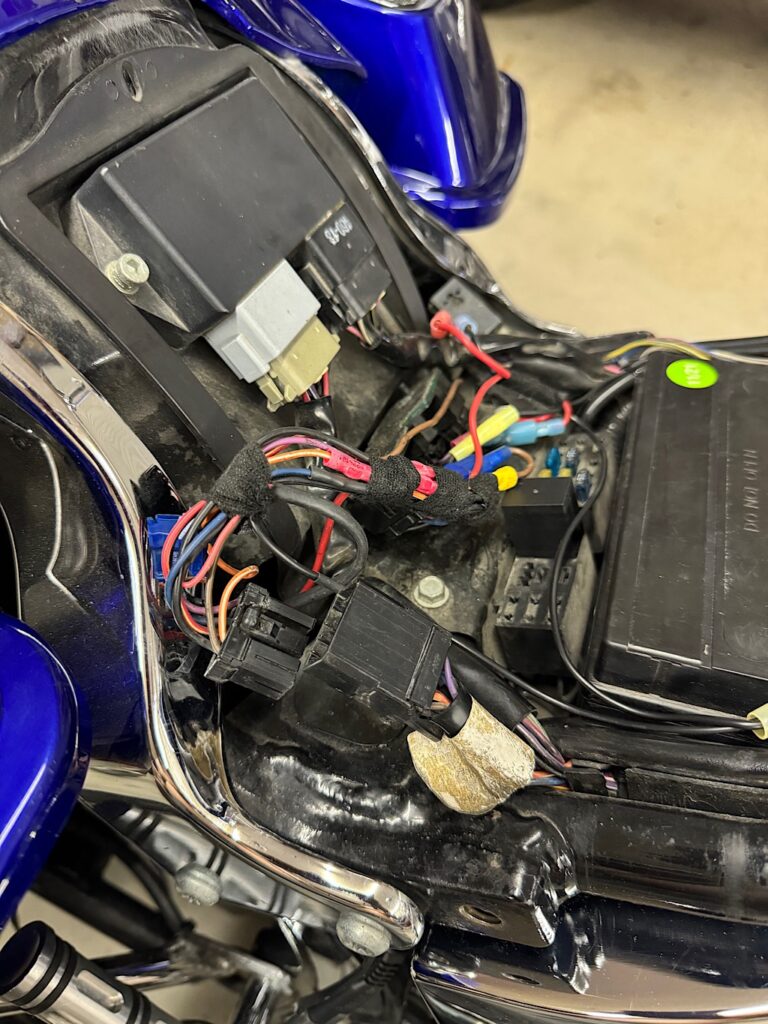
Invoking TSM/TSSM diagnostics

1: Set Run/Stop switch to off

2: Turn ign key ON-OFF-ON-OFF-ON

3: Press the left turn switch two times and release.

*The signals flash 2 times for a Domestic TSSM

4: Press the right turn switch 1 time and release.

*The signals flash 1 time.

5: Press the right turn switch 1 time and release.

*The signals flash 2 times.

6: Press the right turn switch 1 time and release.

*The signals flash 3 times.

7: Press the left turn switch 1 time and release.

*The signals flash out the trouble codes.

There is a 1.5 sec pause between flashes to distinguish between 1st and 2nd digit of codes.

There is a 4 second pause between codes, then it will loop and repeat codes.

If the light comes on for 4 seconds after invoking test then goes out for good,

there are no codes stored…..test over….turn ignition off.

Wait at least 10 seconds

before turning ignition on again.

8: To clear codes (after repairs) press and hold left turn switch for 4-5 seconds at end of test.

* The signals flash 2 times to confirm your request.

Codes

11= Battery voltage high

21= left turn ouput fault

22= Right turn output fault

25= Ignition enable output high

31= alarm output low

32= alarm output high

34= starter output high

35= accelerometer fault

41= Ignition switch open/low

Possible causes

11= battery voltage >16.0v/battery charger used/voltage regulator fubar’d. (pin 1 / Bn/Gy)

21= bulbs/shorts/bad connections if no voltage on pins 5 or 6 with 4ways on TSSM FUBAR’d

25= should be no voltage present on pin 10 with key off. (Lt Grn/Gy wire on TSSM)

31&32= Middle pin on siren goes low voltage to fire alarm, high voltage to stop.

If the siren responds with 3 chirps instead of 2 the siren battery is fubar’d.

Pin A (Bn/Gy) is positive voltage downstream of the 15amp security fuse.

Pin C (Bk) is ground from pin 12 (Bk) on TSSM

34= Starter relay and coil are grounded via TSSM when disarmed and ignition on.

This code means the ground is from someplace else…short/hot wired..etc.

Starter relay could be fubar’d (voltage present on pin 9)(Tn/Gn) when not starting engine.

35= TSM/TSSM Fubar’d… bank angle and tamper will not function when this code is set.

41= Signals will not flash due to shorts, bad connections/wiring/bulbs/TSSM fubar’d

More notes

*If the siren Chirps 3 times instead of 2 this means time for a new siren battery.

*There can be codes set in the TSSM without any visual indications ie: Security lamp/ Signals

*There needs to be 12.0vdc available from the main battery

*There are 4 sensitivity settings for alarm activation, with regard to motion….lol

*There is an Auto Arming feature available, all domestics are shipped with this disabled.

*Always disarm the TSSM before disconnecting the battery, or siren will activate.(If present)

If auto arming is activated, you have 30 seconds after disarming to pull the fuse

to accomplish the above.

*Tampering or problems with the security light circuit activates the alarm for 30 seconds.

*Storage mode time is selectable, and will shut down system at 30,60,or 90 days, or never.

Key fob will not work after shut down. Turn ignition ON to re-activate, the alarm will sound

if it was armed prior to storage mode shut down. Use the key fob to disable the alarm.

*IF you render the key fob useless and did not program a personal override code in the TSSM,

you are not only buying a new fob, you are buying a new TSSM as well.

Once it learns a key fob, it learns no more..lol
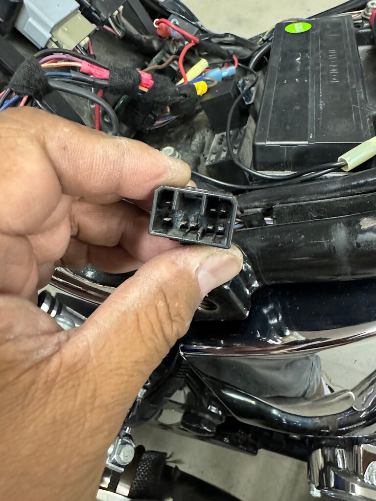
TS/TSSM Pinouts

1= Battery (Bn/Gy)

2= Ignition (Gy)

3= VSS/Serial Data link

4= Security indicator (Bn/V)

5= Left turn Feed (V)

6= Right turn Feed (Bn)

7= Right turn switch input (W/Bn)

8= Left turn switch input (W/V)

9= Start relay Control (Tn/Gn)

10= Ignition enable signal (LGn/Gy)

11= Alarm signal (Lgn/Bn)

12= Ground (Bk)

Fatboy hyper blinker

Ever since I got the sled the blinkers would flash at a high rate and the red key would be displayed on the gauge.

This will occur if the blinker load has changed to a higher resistance which is the case with LED turn signals.

There are a couple ways to fix this situation. The most common way is to add a load resistor (low cost) or to use a load equalizer. The method may cost more but the technology is better and does not dissipate a lot of heat looks the static resistors.

I ordered a set from Amazon and it should arrive tomorrow. The part is a ”bridge” connection.

Connector 8 pin usage.

I will update this blog once I have completed the installation and test functionality.

Below is the actual part. It comes in two colors, black costing a few dollars extra. Since this is an under seat product location it didn’t matter to me the module I purchased was white.

The installation is probably one of the easiest installs or modifications I have done to a sled. This is almost an installation error proof procedure.

The preliminary testing is showing the hyper flash issue no longer a problem. I temporarily placed the module where it fit without getting damaged once the seat is installed.

The next step is to erase the stored Diagnostic Trouble Codes DTC.

After reading a few online forums, some were saying you can reset the history codes by removing the battery negative cable for a few minutes and the codes in history will clear.

I tried this method and it didn’t work. Others were saying you need to have 50 ignition starts and the coffee will clear.

I’ll update this blog post when the codes have cleared. Hopefully I don’t get another set of codes.

Hot weather continuous

Blistering riding weather all week. When it gets this hot there is no comfort from the wind movement. In fact, it’s like you’re riding inside of a giant air fryer. The heat is so intense your sweat is drying faster than you can hydrate which means you can seriously get into trouble on a long ride.

T. emperature measurement taken at Keifer Road, Rancho Cordova. During the remaining ride home I hit temperature of 114. This was just before you get into the town of Ione.

I try to prepare myself the best I can before hitting the road. This included drinking a lot of water and eating ice chips.

Hot weather riding

During transition from the cooler weather to flat out hot I will tend to to not wear full gear that I would normally wear during the winter months.

For about 2 weeks I rode home wearing just a short sleeve shirt. This was under very hot conditions with the sun blasting me every mile I rode.

My arms are the only exposed skin parts minus a small section on my face that is not covered by the helmet.

You can see the intense redness after another hot 100+ temperature ride. My arm looks like it is swollen and very red in color.

My wifey and I purchased long sleeve shirts.

Pulse Generator

I thought I’d use the term Pulse Generator instead of the other commonly used “ignition pulse crankshaft position sensor”.

I started this Friday evening to get a start on the tear down.

The front upper and center cowling requires removal to perform this project. I didn’t have to remove the front fender, I drape a towel over it for some form of protection.

Once the front plastic pieces are removed you’ll see the regulators and purge valve located at the upper section as shown in the photo below. I have the non-ABS model and it is not necessary to go from above to access the Pulse Generator 2P connector. Everything will be done from the front of the engine.

The following instruction was taken from an online Goldwing forum. I did not create this procedure but I can say it is what I used to perform the part replacement.

Here are the instructions from Greg:

“If you have ABS, you’ll need to pull the tank and air box to get to the 2P connector.

If not, remove the upper center cowl, the single bolt and vacuum hose, to allow the canister’s purge control solenoid to fall. Then unplug the on each side. Wrap the coils in a towel and allow the coils to fall on the the back part of the front fender. That should then give you access to the boot the connector is in”.

Once the purge valve and regulator housing has been loosened and moved forward the Pulse Generator 2P is accessible for removal.

The 2P is bundled with a few others wrapped in a dust boot. You will need to slide the boot cover out of the way to unclip the mating connector.

To access the pulse generator, the timing cover will need to be taken off. This is done by removing the 12 cover screws. You do not need to remove the crankshaft center dust cap. The cap can stay in place during the entire process.

In my case the timing cover has probably never been taken off. It was difficult to remove by hand. I ended up having to use a large blade screw driver to pry the cover off.

As expected pieces of the original gasket remained in place. With a bit of elbow grease and soaking the cover inside my parts cleaner tub, I was able to remove all the pieces.

Using a part cleaner tub makes a the job much easier.

The engine housing also required gasket material removal. Since I’m not able to have the same luxury with the chemical tub application I used engine bay cleaner to soak the remain8g pieces. I take my time whenever I work on projects for the first time.

Case cleaned up and ready for the new part.

The pulse generator will be prewired to a 2P connector. I went ahead and bolted the part down and positioning the wires through the slotted opening. Once that is complete you can lay the gasket onto the timing cover using the 2 dowels for gasket alignment.

The installation procedure is essentially doing everything in reverse order. After buttoning the timing cover back in place and securing the regulators and purge valve I did a test start. It fired right up.

After installing the remaining pieces I gave the sled a wash. All ready for the next ride!

Ignition crankshaft position sensor

I thought this was a good place to use as a storage reminder for the replacement project later this weekend.

I ordered the recommended sealant, actually it’s “YamaBond 4” instead of the recommended HondaBond 4. I couldn’t get the Honda brand in time for to work on the bike this weekend. It’s scheduled to arrive by tomorrow.

The diagram is showing only 2 locations requiring the sealant. This is a dust gasket and not designed for fluid.

The actual Pulse Generator part is shown attached to the rear side of the timing cover.

Motorcycle table lift

Picked up another hardware piece needed to secure a sled down. The adjustable base platform stabilizes the bike from the middle. This is used with the front straps.

The base jack is also used when the rear tire needs to be removed. At some point I will do a cutout on the rear side of the platform for a “drop down” access section.

I’ll be removing the cafe bike and loading up the Goldwing. The ignition crankshaft position center seems to be getting wonky and needs a new part installed.

Stepping up

I’ve been wanting a nice motorcycle table lift and when I saw one at a local yard sale at a good price I knew I had to go for it.

This is not a cheap harbor freight type of lift, it’s manufactured by a well known company that has been in the business for many years.

The 1982 Honda 450 CM had the honors of being the first bike on the lift.

One modification I plan on doing is the rear of the table top there’s no drop down access door. This feature is useful when removing a tire from bikes that have a fairing or fender bags blocking the way.

Ignition crankshaft position sensor

Parts for the ignition crankshaft sensor replacement. The official name of this part is the Pulse Generator. That will be the name used by Honda when ordering the part.

In order to get to the crankshaft position sensor the front lower cowl will need to be removed. A new gasket will be necessary.

So why am I replacing this part? From the research I’ve done the issues I have been having are related to the pulse generator. The symptoms are intermittent starting issues. The starter motor will crank like normal but the bike will not fire up. It keeps on turning over.

Some guys are saying a weak battery will do this and that’s a possibility since the battery I have is probably the original. I do keep the battery on a maintainer when not in use. So this is a slim possibility.

I will change out the part first to see if the intermittent problem completely goes away.

Note * I rode all last week without the starting issue so this is not an easy problem to troubleshoot.

Front tire change

I think this is one of the few time I’ve changed the front tire and there are no visible white tread showing thru. For record keeping the mileage count is 61804 miles.

I decided to go with the E4 series tires.